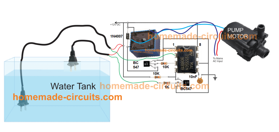
Closed circuit water relay.
Closed circuit water relay system.
This diagram shows an active spdt relay with power applied to pins 85 and 86.
A direct open circuit cooling tower is an enclosed structure that distributes warm water over a labyrinth like packing or fill which provides an expanded air water interface for heating of the air and evaporation to take place.
Pin 30 common and pin 87a normally closed are connected.
The above terms are interchangeable and refer to systems operating.
There are two types of water relays commonly referred to and used.
Closed system terms functions.
Mthw medium temperature hot water system.
Lphw low pressure hot water systems.
Our closed loop water treatment solutions address the problems of corrosion fouling biofouling and scaling that.
The water is cooled as it falls through the fill and is then collected in a cold water basin below.
The second pump may in turn be connected to the inlet of a third pump and so on until water is delivered to the fire ground.
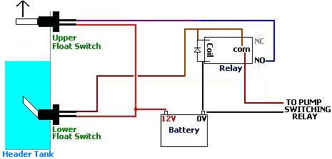
Closed circuit water relay in which the water is pumped through hose direct from one pump to the next.
5000 sets are already in operation with satisfactory results.
A water relay comprises a number of pumps spaced at intervals along a route between a water source and the point where the water is required.
Lthw low temperature hot water systems.
This prevents the cooling water from picking up particles that may not get filtered or even dissolved gases.
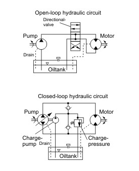
Certain processes require a closed loop whereby the process water for cooling does not come in contact with the atmospheric air.
Closed circuit cooling systems.
The above terms are interchangeable and refer to system operating up to about 90 o c and pressures of about 3 4 bar.
This circuit diagram of an inactive spdt relay with no power applied to pins 85 and 86 ground and 12 volt positive.
Closed circuit industrial coolers water systems with closed circuit industrial coolers have many advantages and are ideal for cooling in any climate for a wide variety of reasons.
Reasons include no condensation problems no coolant contamination and minimum corrosion scaling and electrolysis.
Electronically controlled ccrs can be switched to manual control in the event of some control system failures.
A closed circuit water relay is when water is pumped at the water source through hose lines connected directly to the inlet of a second booster pump.
Mphw medium pressure hot water system.